How exactly does one set up a mum garden? Examine the space requirements, equipment needed, plot layout and tools. This section lays out how to implement a successful irrigation system for growing chrysanthemums.
The Plot
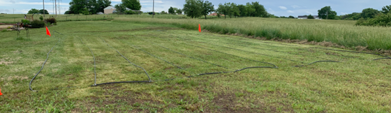
Select a plot that is relatively flat ground. Hills can be used, but this could create other challenges. Mums require a tremendous amount of water. Select a location conveniently close to a water source. The site I selected was a grassy relatively flat area. There is a slope to one side.
Plot Layout
The grass can be removed or will eventually rot under a ground cover. Make sure the entire area is flat with no dips or recessions to make walking easier.
Layout
The plot size is determined by how many plants you plan to have. Our first year we planted 400 mums, the second year 650, and the third year 1,000. The layout and calculations for this website is based on 1,000 mums. The number is easily divided or multiplied for the number of mums you want to grow.
Mum crowns grow to approximately twice the diameter of the top of the pan they are grown in. We use a 9” pan which makes each crown approximately 18” in diameter. If the crowns touch, the foliage growth in that area will be stunted and cause inferior looking mums. Therefore, we space each mum pan 22” apart [18” for the crown plus a 2” space ring outside of that.
If the mums are offset, they can be grouped closer together which reduces the total area of the plot.

Mum Offset Example
As the plants grow, walking between them to tend and inspect growth may become difficult if an aisle is not provided. We put an 18” aisle between each two rows.
Ground Cover
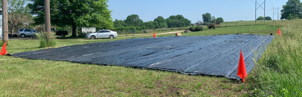
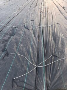
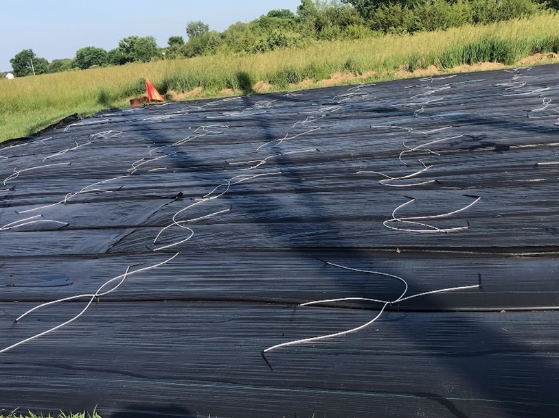
The weeds and grass need to be kept at bay. We tried various geotextile fabrics for the area. This ground cover fabric comes in various widths, lengths, thicknesses, and lifespans. Overlap the fabric by 6” or better.
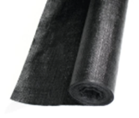
6′ X 100′ Geotextile Fabric
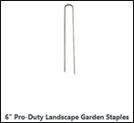
Use ground stakes to keep the fabric in place. Using wider rollers of fabric reduce the number of ground states required to keep the fabric in place. When the water lines are added, they will be held in place with the same stakes which will help keep the geotextile in place. A strong wind can lift the fabric if plants aren’t in place yet or during the winter break. I use old tires to help keep the fabric in place during the off season.
Water Line Layout
Mums need water, food and other growing essentials. The easiest way to provide this is with irrigation water lines. There are several different methods to accomplish this. We chose to use central water transmission lines and ‘spiders’ to provide each individual mum pan.
The water line we use is polyethylene pipe. Various sizes are used to facilitate water flow. The goal is to provide equal pressure to all mums at the same time in the distribution system. We achieve that by looping the water feed system.
Geotextile ground cover fabric in place with water lines
The waterline distribution network is designed to provide the same water pressure to all of the plants during the watering process. There are a number of designs possible. My design uses a ¾” polyethylene pipe on the outer laterals and then ½” polyethylene pipe on the interior laterals. I make the middle lateral ¾” to help reduce pressure drop in the pipes. Orient the pipes in the network perpendicular to the slope of the plot. This will keep the food and water from concentrating on the down slope of the network..
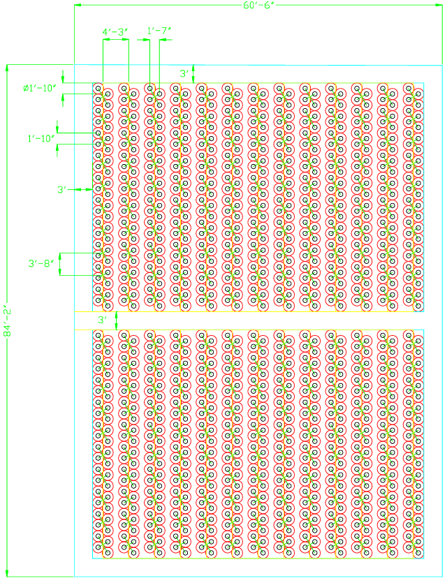
The network is laid out as shown below. There are two independent networks each supplying water and fertilizer to 500 plants. The overall size of the network is 77’ X 54’. Each plant is expected to have a crown of 1’-8”(20”). Each plant is spaced 1’-8” apart. The lateral lines are spaced 4’-1” apart. The space between the plants (walkway) at full maturity is 11 3/4”. There is a 3’ walkway all around the outside of the plants.
The laterals on the perimeter of the network are ¾” pipes. There are 11 laterals on the inside of network. Ten of those laterals are ½” pipes. The center lateral is ¾”. There are no dead end pipes.
Distribution Elements
We use the Netafim irrigation system for providing water to the mums. At regular intervals along the poly pipes, drippers are installed to distribute water to the plants. The interval is dependent on how far the mums are spaced apart. Our mum spacing will require the installation of each dripper to be located 40” apart. A concept overview of that layout is shown below.

Feeder Layout with Drippers and Hoses
At each interval a pressure compensating dripper is inserted into the pipe. Drippers are designed for varying flow and various configurations of drip lines. We chose the 2.0 gpm drippers designed to accommodate the 4-way distribution manifold. The drippers require at least 14.5 psi to maintain the constant 2 gpm flow. This is a critical part of calculating the water flow for the overall system.
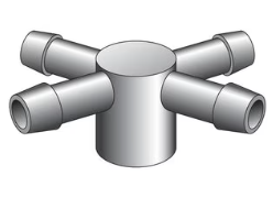
Dripper and 4-Way Distribution Manifold
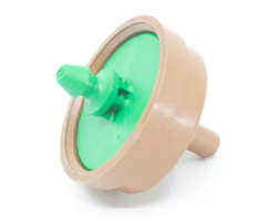
The manifold connects to a small hose from each arm which connects to the actual dripper. Drippers come in short and long lengths. We use the longer length to keep them in the soil. The shorter one would likely work as well as the longer one.
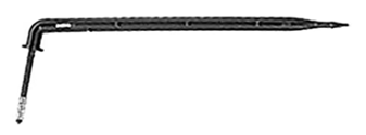
Angle Dripper
The manifold, hoses, and drippers can be obtained pre-assembled or purchased separately. We chose the pre-assembled units.
Water Line with Spiders and Woodpeckers
Irrigation Liquid Supply System
The water for the distribution system is supplied to the irrigation lines described above. There are several documents on the internet that discuss the design of an irrigation system. Some are well written, and some are extremely difficult to comprehend. Our website is intended to show you how we successfully put together a useable irrigation system for mums. The final element of the irrigation system is the pump and fertilizing equipment. The diagram below shows the general layout of the equipment used in fertilizing and irrigating.
Daily feeding follows the same general steps. Water and fertilizer are mixed in the 5-gallon bucket. The bucket is set below the fertilizer injector inlet and is combined with incoming water at a specified ratio. The water is turned on at the faucet. Water flows through the injection system, collects the fertilizer/water mix and then out into the supply network. Water and fertilizer are delivered to each manifold and then to each plant. The system has a drain valve at the lowest elevation of the supply network to drain the fertilized water at the end of the feeding. Drain the network after each feeding or fertilizer salts build up at the manifolds. Monitor the overall system pressure by checking the pressure gauge installed at the farthest point in the network from the injection point. The system pressure must be above 14psig for the drippers to work properly.
Our injection system setup looks similar to the diagram below. The chart below the diagram shows the purpose of each element of the system.
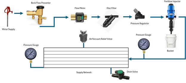
|
ITEM |
PURPOSE |
NOTES |
|
Water Supply |
Provide water
to mums. |
Calculate
flow and determine line pressure. |
|
Back Flow
Preventer |
Keeps
chemicals from flowing back into a potable water supply systems. |
Required in
most public water supply systems. |
|
Water Flow
Meter |
Confirm water
delivery per feeding. |
This is a nice to have not an absolute necessity. |
|
Disc Filter |
Filters out
particles in the water supply that could plug the system’s drippers. |
Use at least
an 80 mesh filter.
Keep a spare filter on hand so one can be
cleaned while one is in use. |
|
Pressure
Regulator |
Reduces water
supply pressure to acceptable range for irrigation system. |
Keep the
pressure in the distribution network between 15 and 45 psig. |
|
Fertilizer
Injector |
Mixes
fertilizer solutions with water. |
The
calculations for the fertilizer master mix are provided in another section. |
|
Pressure
Gauge One |
First
pressure gauge monitors inlet water pressure. |
Drippers have
a maximum water pressure allowed so that they work correctly. |
|
Air/Vacuum
Relief Valve |
Allows air to
escape from the distribution piping so all feeders are supplied with water. |
Place at
highest point in the distribution system. |
|
Pressure
Gauge Two |
Farthest
pressure gauge monitors lowest water pressure in the
system. |
Place gauge 2
at the farthest point in the supply network from the water inlet to the
network. Maintain a minimum pressure
at this point. |
|
Drain Valve |
Place at the
lowest point in the irrigation network. |
Drain the
irrigation network at the end of each feeding and at the beginning of the new
feeding to keep the lines clear of salt build up. |
Water Distribution System Calculations
As mentioned earlier, the goal is to provide each plant with the correct amount of water. The drippers will provide 2.0 gallons of water per hour to four plants or 2 quarts of water per hour per mum. We feed our mums at least one quart of water per day in normal weather conditions and two quarts of water per day during exceptionally hot weather conditions. That means we will water the plants for 30 minutes.
The planted area is divided into two parts with 500 plants in each part. For 500 plants, 125 gallons of water will be required for each watering [500 plants X 1 quart per plant / 4 quarts per gallon = 125 gallons]. After multiple trials and testing we determined that our plants require 30 minutes of water each day to keep the soil moist, or 4.16 gallons per minute [125 gallons / 30 minutes = 4.16 gallons per minute].
The water supply used was tested to determine the rate of supply. A five-gallon bucket was placed under the faucet and timed to determine time required to fill the bucket. The bucket filled in 43 seconds (0.714 minutes) which means the water supply can provide 7 gallons per minute [5 gallons / 0.714 minutes = 7 gallons per minute]. This will be adequate to feed 500 plants (but not the 1,000 being planted at the same time).
The 14.5 psig pressure required throughout the network should be calculated. This is a fairly deep engineering subject and not for the faint of heart. Suffice it to say, if you have water pressure and flow close to what I have, you will be able to supply enough pressure for 500 plants. If on the other hand you want to delve into the finer art of water pressure calculation, I found this YouTube article to be quite informative: DEMO: Hardy Cross Method (MS Excel) to determine flow rate and pressure for an example pipe network.